


In the field of plastic product processing, fiber-filled components have attracted significant attention due to their unique performance advantages. When glass fibers or carbon fibers are cleverly blended with resins, the physical properties of the plastic undergo significant changes. Its elastic modulus and tensile strength are greatly enhanced, which makes the originally flexible plastic parts become rigid and possess stronger load-bearing capabilities. Even when a heavy load is applied to the plastic parts, they can effectively resist deformation and maintain a stable shape thanks to their increased rigidity.
However, this performance improvement is not without its drawbacks. The impact strength of fiber-filled plastics is relatively low, making the components brittle and prone to breakage, with a significantly reduced ability to withstand impacts. At the same time, their flow properties are also affected. During the injection molding process, the shrinkage of the plastic in the flow direction is less than that in the direction perpendicular to the flow, and this anisotropic shrinkage poses challenges for mold design and molding quality management.
In the actual operation of injection mold design, setting the shrinkage rate is a major challenge. Since it is difficult to accurately set the shrinkage based on the plastic flow direction at the gate, and CAD software only allows users to set the shrinkage rate in the X, Y, and Z directions, when dealing with parts with large dimensions and strict tolerance requirements, some dimensions are highly likely to exceed the allowable tolerance range. This dimensional deviation not only affects the assembly accuracy of the parts but may also reduce the overall performance and quality of the product.
To address this challenge, a common approach is to reserve more mold steel to ensure a safety margin. The excess mold steel can be easily removed through CNC machining or electrical discharge machining. However, once too much steel is removed, it becomes extremely difficult to add more. To do so, welding operations are required on the injection mold. But the welding process often comes with the risk of mold deformation, which not only shortens the service life of the mold but also harms the quality of the molded parts, such as causing surface defects and reduced dimensional accuracy.
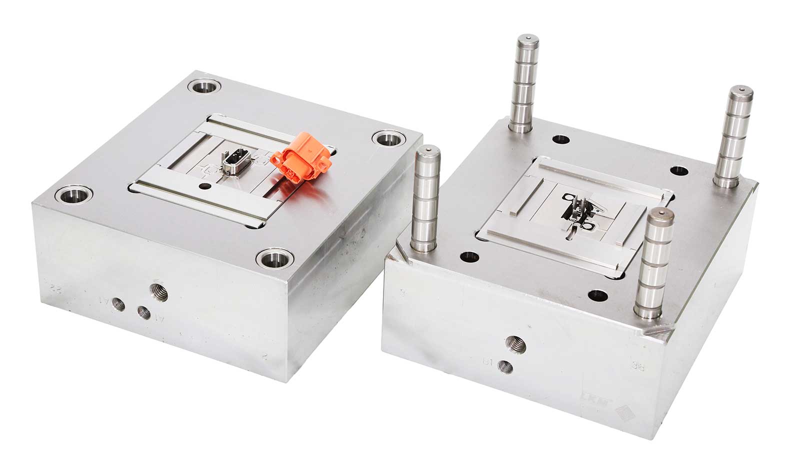
Regarding mold modifications, when the dimensions of plastic parts exceed the tolerance range, it is usually necessary to remove or add a certain amount of steel from the mold to change its shape or dimensions to meet the design requirements. However, this process is cumbersome and costly, and may introduce new quality issues. To avoid frequent mold modifications, manufacturing experimental molds has become a key method for testing the rationality of injection mold designs.
Specifically, first manufacture an experimental mold, obtain plastic part samples through this mold, and then carefully compare the critical dimensions of the plastic parts with the design print results. If any key dimensions are found to exceed the tolerance range, corresponding changes need to be made to the production mold. The core purpose of experimental molds is to determine in advance which dimensions may exceed the tolerance and which key features meet the design requirements. Once the specific impact of different shrinkage in different flow directions on dimensions is clarified, precise adjustments can be made when manufacturing the final hard mold, thereby effectively improving the accuracy and reliability of mold design, reducing production costs, and enhancing product quality.