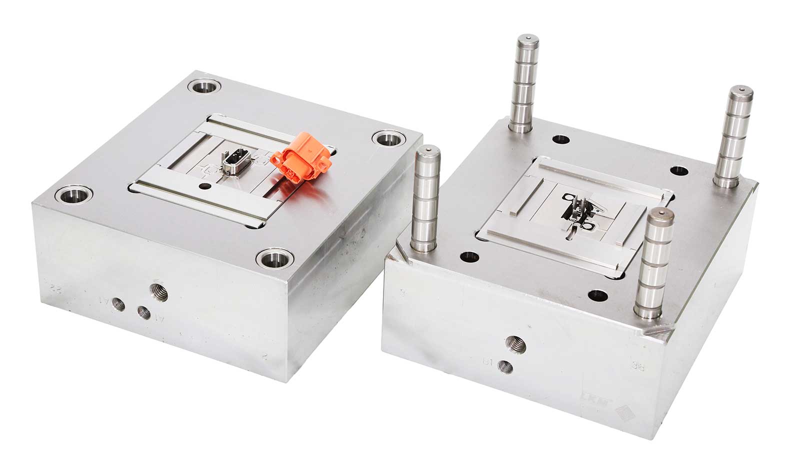


In the realm of injection mold design, the determination of cavity quantity and layout design stands as a “cornerstone task” that directly impacts mold manufacturing costs, production efficiency, and product quality stability. This article systematically dissects the seven core factors governing cavity quantity and layout design, offering actionable insights for practitioners in the industry.
1. Cavity Quantity: The Art of Precision Balancing
Cavity quantity optimization requires striking a delicate equilibrium among technical feasibility, economic viability, and product quality. The following seven factors form the decision-making matrix:
-
Part Weight vs. Injection Unit Capacity:
The weight of a single part and the injection unit’s maximum shot capacity determine the upper limit of cavities. For instance, if a single part weighs 150g and the injection unit’s maximum shot capacity is 300g, the maximum cavity count is two, with a 10%-15% safety margin reserved for material density fluctuations to avoid defects like flash or short shots. -
Projected Area vs. Clamping Force:
The projected area (including the runner system) and the injection machine’s clamping force must satisfy the formula:
F (Clamping Force) ≥ A (Projected Area) × P (Cavity Pressure) × Safety Factor.
For example, if a part’s projected area is 200cm², cavity pressure is 30MPa, and the safety factor is 1.2, the required clamping force is ≥720 tons. If the injection machine’s clamping force is only 500 tons, cavity count must be reduced or runner design optimized. -
Mold Size vs. Machine Capacity:
The mold’s external dimensions (length × width × height) must strictly comply with the injection machine’s mold capacity (tie bar spacing × platen thickness). For instance, if a mold measures 600mm × 500mm × 400mm and the injection machine’s minimum mold space is 550mm × 450mm × 350mm, cavity layout adjustments or equipment replacement may be necessary. -
Color Variations and Process Barriers:
Multi-color/multi-material parts require technologies like rotary tables or hot runner valve gates. For example, suppose a product necessitates two-color injection with a melting point difference exceeding 50℃. In that case, cavity count must be adjusted based on color-change efficiency and thermal balance needs, typically resulting in fewer cavities for multi-color parts. -
Side Action Mechanisms and Space Conflicts:
Side actions (such as lifters or slides) significantly increase mold complexity and size. For instance, if a part requires three side actions, each occupying 80mm × 50mm, cavity spacing must be ≥150mm, potentially reducing cavity count by 30%. -
Production Volume and Investment Payback Period Synergy:
High-volume production (annual demand >500,000 units) favors high-cavity molds (>16 cavities) to amortize mold costs; low-volume customized production (annual demand <50,000 units) prioritizes 2-4 cavity molds to reduce trial risks and inventory pressures. -
Economic Viability: The Profitability Balance:
The production value per mold must cover mold amortization costs (mold cost ÷ production cycles) + per-unit processing costs. For example, if a mold costs 800,000 RMB and plans to produce 100,000 molds, each mold must generate at least 8 RMB in profit. If per-cavity profit is only 0.5 RMB, cavity count must be ≥16 to break even.
2. Cavity Layout: The Core Logic of Systematic Design
After determining cavity quantity, layout design must integrate five dimensions to maximize mold performance and production efficiency:
-
Mold Size and Structural Optimization:
Adopt “H” or “X”-shaped layouts to minimize platen deformation and reduce residual stress through cold slug well designs in the runner system. -
Runner System Balancing:
Calculate the main runner diameter using the formula D=1.25×(shot weight/runner length)^0.33 to ensure a filling time difference of <0.05 seconds across cavities. -
Side Action Mechanism Synergy:
Side action directions must form a 15°-30° angle with the mold opening direction to avoid motion interference. -
Insert and Core Modular Design:
Implement a “core cavity + replaceable insert” structure to reduce mold changeover time by >40%. -
Cooling System Precision Matching:
Maintain cooling water channels 8-12mm from the cavity surface with a flow rate of ≥0.8m/s to ensure a temperature difference of ≤3℃.
3. Industry Insights: Trends from Case Studies
Take a Dongguan-based precision electronics enterprise as an example. Its Bluetooth earphone shells (8g each, annual demand of 2 million units) achieved cost reduction and efficiency gains through the following optimizations:
- Cavity Count: Upgraded from 8 to 16 cavities, reducing mold cost amortization by 35%.
- Layout Design: Adopted a spiral runner + pin gate design, reducing filling time differences from 0.12 to 0.03 seconds.
- Economic Viability: Increased production value per mold from 12 RMB to 25 RMB, shortening the investment payback period to 8 months.
Conclusion: Data-Driven Mold Design Upgrades
The decision-making process for cavity quantity and layout design in injection molds is essentially a triangular balance between technology, cost, and market demands. By establishing parametric calculation models (e.g., cavity pressure prediction algorithms, runner balancing simulations) and leveraging CAE tools (such as Moldflow, SolidWorks Plastics), design efficiency can be improved by >50%.
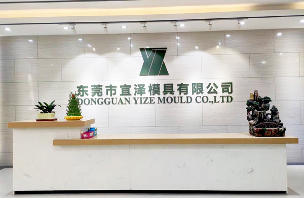
About Us
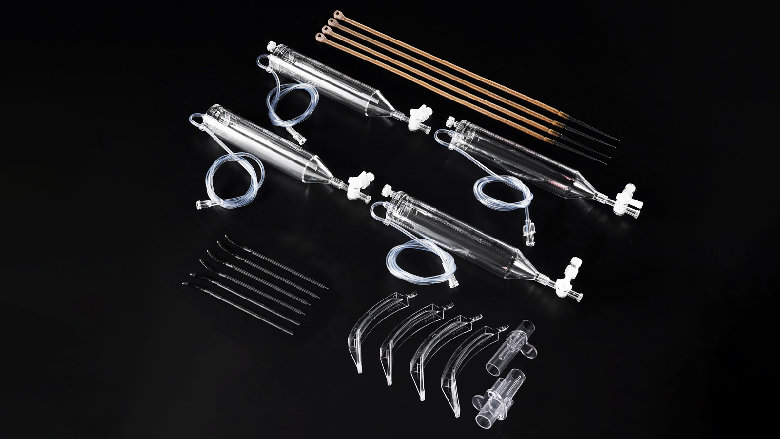
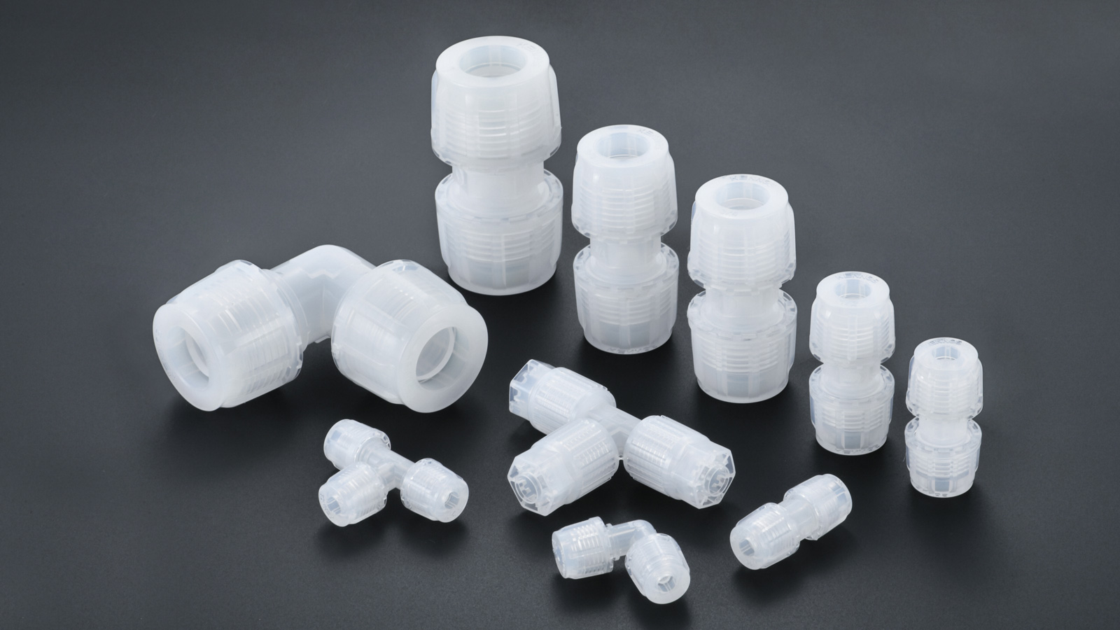
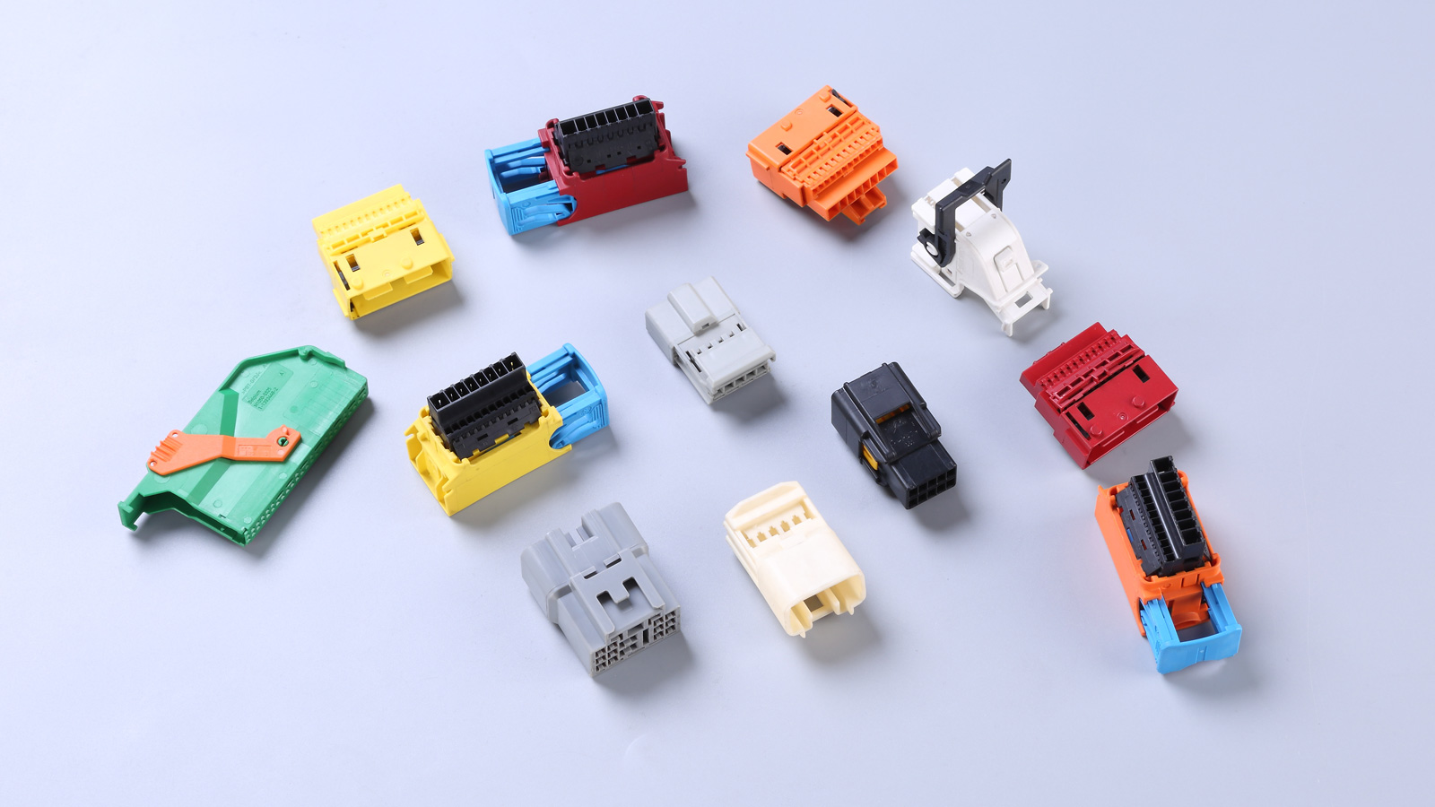
Dongguan Yize Mold has specialized in precision injection molds for 18 years, serving clients in automotive electronics, medical devices, and consumer electronics. If you face challenges in mold design optimization or process cost reduction, contact us at +86-133-0261-5729 or scan the QR code for the Injection Mold Cavity Design White Paper. We provide end-to-end solutions from DFM analysis to mass production.