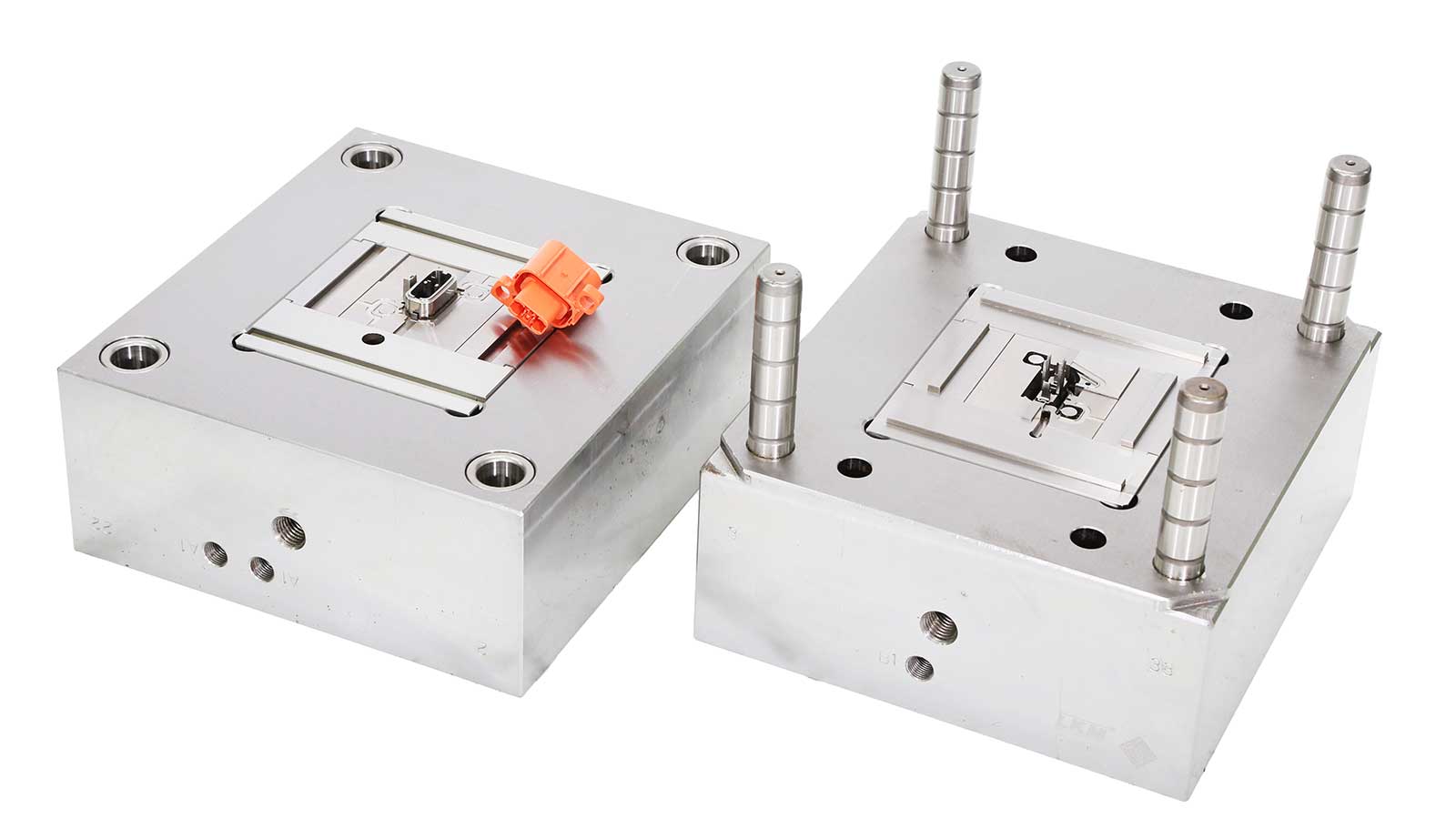
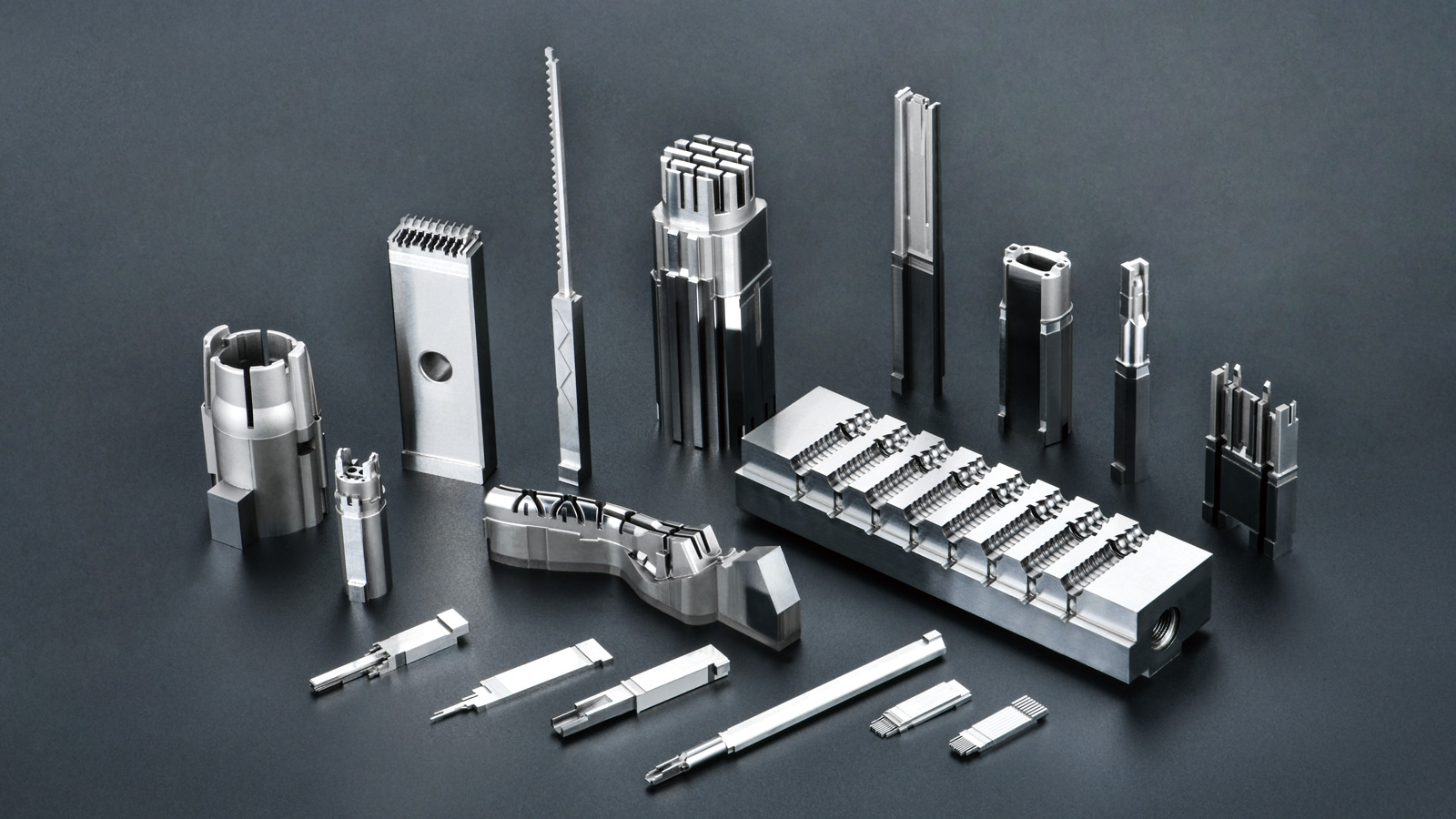


In the field of injection molding, the design of the parting line stands as the “soul decision” of mold engineering. It serves as the boundary between the plastic part and the mold, directly dictating mold complexity, manufacturing costs, product yield rates, and production efficiency. With 15 years of expertise in precision mold manufacturing, Yize Mold’s engineering team has distilled five core principles to help you avoid pitfalls and optimize mold production.
1. The “Zero Compromise” Principle for Aesthetics and Function
Core Logic: The parting line must be hidden in “visual blind spots” or non-critical functional zones.
- Case Studies:
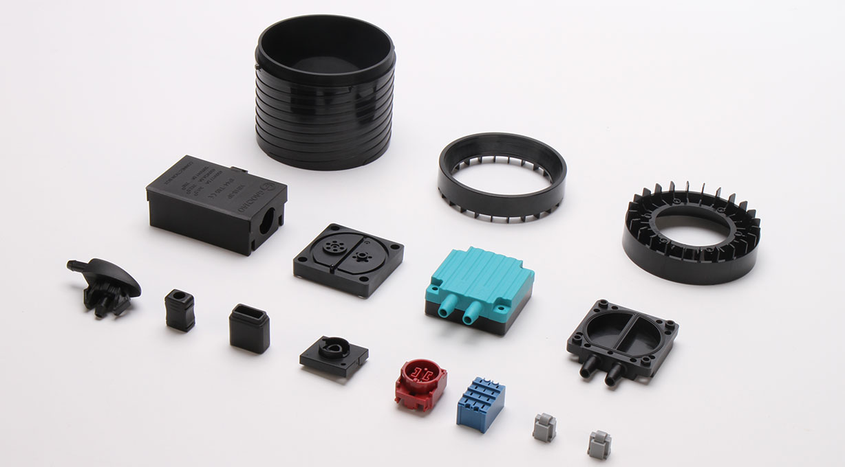
- For home appliance casings, parting lines are often placed in side grooves or bottom seams to avoid surface scars.
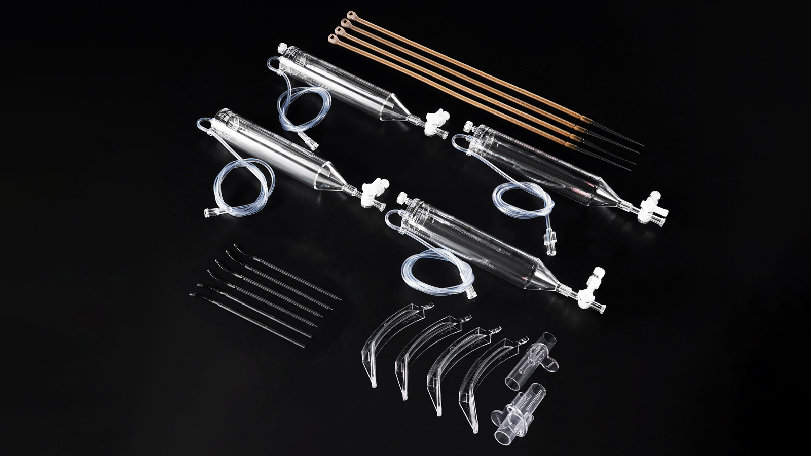
- Medical device casings must avoid keypad areas and display bonding zones to prevent burrs from compromising sealing.
- High-end electronics (e.g., smartphone frames) adopt “hidden parting lines + polishing” for seamless aesthetics.
- Engineer’s Advice: Use 3D modeling to simulate parting line projections and collaborate with clients to define “acceptable zones,” avoiding costly post-design modifications.
2. The “Dual Optimization” Principle for Precision and Efficiency
Core Logic: Parting line design must simplify mold processing while ensuring dimensional stability.
- Key Strategies:
- Simplify Cavity Geometry: Prioritize flat or slightly curved parting lines to reduce CNC machining and EDM complexity.
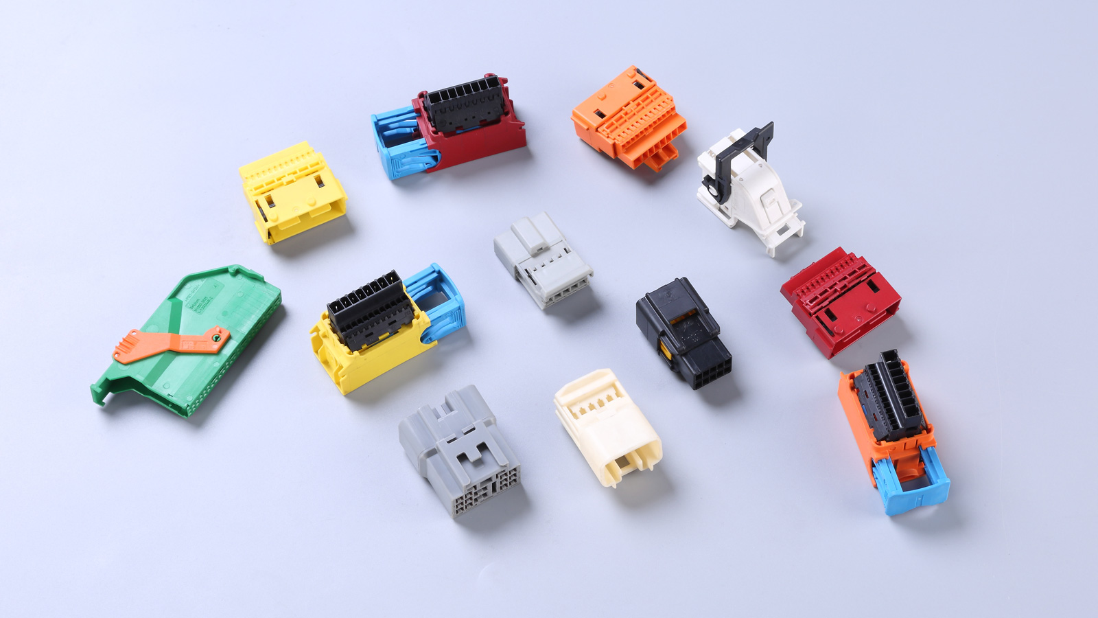
- Avoid Thin-Wall Sharp Corners: In thin-walled parts like automotive grilles or electronic connectors, parting lines must bypass sharp corners to prevent short shots or flash.
- Predict Warpage Risks: For elongated or irregular parts (e.g., LED lamp covers), optimize parting line angles via CAE simulation to counteract warpage from ejection stress.
- Data Support: Proper parting line design can cut mold processing cycles by 30% and maintain dimensional tolerances within ±0.02mm.
3. The “Trinity Integration” Principle for Runner, Venting, and Cooling
Core Logic: The parting line serves as the “strategic hub” for runner system design, balancing melt flow, gas exhaust, and heat exchange.
- Technical Highlights:
- Runner Balance: Align parting lines with main and branch runner layouts to ensure uniform filling in multi-cavity molds (e.g., dual-color smartphone cases).
- Venting Optimization: Install vent slots in deep ribs or blind holes, maintaining parting line gaps of 0.03–0.05mm to prevent gas traps and burn marks.
- Cooling Efficiency: Reserve space for conformal cooling channels near parting lines. For large parts (e.g., AC panels), adopt “spiral + baffle” water circuits to limit temperature variance to ≤±2°C.
- Engineer’s Warning: Neglecting venting design can spike defect rates above 15%.
4. The “Damage-Free” Principle for Ejection and Handling
Core Logic: The parting line must pave the way for ejection mechanisms, ensuring intact part removal and easy handling.
- Design Essentials:
- Directional Retention: Control part retention on the moving mold side via parting line draft angles (typically 2°–5°) to avoid sticking to the stationary mold.
- Ejection Redundancy: Add auxiliary ejector pins near undercuts or deep ribs, reserving ≥5mm ejection clearance at the parting line.
- Human-Robot Synergy: For automated lines, align parting lines with robotic gripper access zones (e.g., avoiding strap connectors on smartwatch cases).
- Industry Practice: A new energy battery housing mold improved production efficiency by 40% through optimized parting line-ejection coordination.
5. The “Dual Safeguard” Principle for Inserts and Operator Safety
Core Logic: For molds with metal inserts (e.g., nuts, sensors), parting lines must balance operational space and safety.
- Technical Specifications:
- Insert Positioning: Reserve ±0.01mm tolerance guide slots at parting lines to prevent misalignment during injection.
- Poka-Yoke Design: Use shaped inserts + parting line limiters to eliminate human assembly errors.
- Safety Margins: In high-pressure injection scenarios (e.g., automotive engine bracket molds), install blast shields at parting lines to prevent insert ejection injuries.
- Case Reference: A medical device mold boosted assembly yield from 85% to 99.5% via parting line insert error-proofing.
Conclusion: Parting Line Design as the “Genetic Engineering” of Molds
Yize Mould‘s Technical Director emphasizes: “Excellent parting line design is the optimal solution to the ‘impossible trinity’ of cost, efficiency, and quality.”
Interactive Benefits:
If you face parting line challenges (e.g., flash at runner junctions, insert encapsulation failures), leave a comment or call +86-13302615729 for a 1-on-1 technical diagnosis from Yize Mold’s engineers!