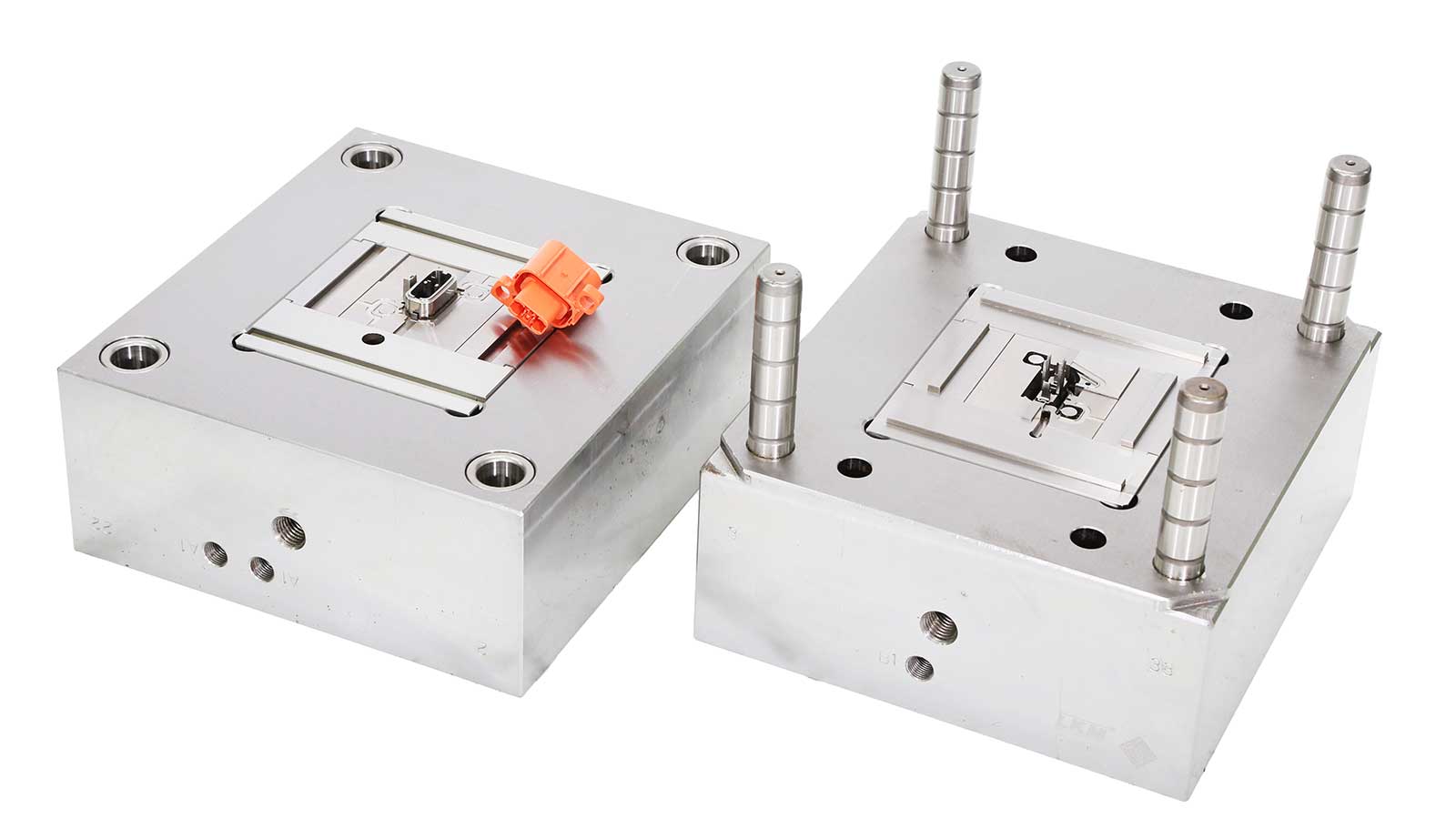
In injection mold development, the runner system design serves as the “vascular engineering” of the mold, directly determining product yield, production efficiency, and cost. This article adopts a “total-to-part” structure to systematically dissect the core logic of runner system design, synthesizing 20 years of industry experience from Yize Mould to refine nine golden rules for gate positioning, helping mold engineers avoid design pitfalls and create efficient injection molding solutions.
I. Overview: The “Three-Dimensional” Core of Runner System Design
The runner system design encompasses three critical modules:
- Runner topology planning (main runner/branch runner layout)
- Precise gate positioning (location/type/cross-sectional dimensions)
- Dynamic balance optimization (melt flow resistance control)
Among these, gate positioning design is the “keystone”, requiring adherence to the principle of “quality first, efficiency balanced.” Below are nine practical design rules.
II. Detailed Rules: 9 Golden Rules for Gate Positioning
Rule 1: Parting Surface Priority – The “Convenient Path” for Mold Processing
- Core Logic: Gates should be prioritized on parting surfaces to facilitate CNC machining and automatic demolding.
- Avoidance Guide: For submarine gates, reserve ≥0.3mm ejection clearance.
- Case: A household appliance housing mold incurred 30% higher processing costs due to misaligned gates.
Rule 2: Equidistant Flow Distribution – The “Fair Racecourse” for Melt Flow
- Technical Parameters: Distance deviation from gate to cavity ends should be ≤5% (for multi-cavity molds).
- Design Tool: Use Moldflow to simulate melt front arrival time differences (target ≤0.1s).
- Counterexample: A 12mm length difference in an automotive lampshade mold caused 8% shrinkage variation.
Rule 3: Smooth Flow Principle – The “Expressway” for Plastic Melt
- Structural Requirements: Implement R0.5–1mm fillet transitions between gates and cavities.
- Material Adaptation: For high-viscosity PA66, transition section length ≥3× diameter.
- Verification Method: High-speed photography to eliminate “jetting-snaking” flow anomalies.
Rule 4: Thick-Wall Priority – The “Pressure Buffer” for Injection Process
- Scientific Basis: Thicker sections provide 3–5s shrinkage compensation windows.
- Typical Application: A smartphone mid-frame mold reduced shrinkage cavities by 67% via rib-mounted gates.
- Prohibition Scenario: Thin-walled products (<1.5mm) require fan gates for pressure dispersion.
Rule 5: Core/Insert Protection – The “Protective Barrier” for Precision Structures
- Risk Control: Maintain ≥5mm clearance between gates and cores/inserts or use horn gates.
- Innovative Solution: A medical catheter mold reduced insert deformation to <0.02mm via spiral buffer runners.
- Data Support: Direct-impingement gates cause 3.2× higher core deflection risk.
Rule 6: Weld Line Management – The “Lifeline” for Product Strength
- Positioning Strategy: Direct weld lines to non-functional zones (e.g., decorative grooves).
- Process Synergy: Adjust mold temperature gradients (-5°C) to relocate weld lines.
- Inspection Standard: CT scans verify fiber orientation at weld lines (tensile strength ≥85% of base material).
Rule 7: Downstream Venting – The “Green Channel” for Gas Escape
- Design Key: Align gate direction at 45° to cavity vents.
- Innovative Structure: An e-cigarette housing mold reduced trapped gas defects by 90% via “fishbone” vents.
- Verification Tool: Infrared thermography monitors gas retention during late-stage filling.
Rule 8: Stealth Gate Principle – The “Aesthetic Code” for Surface Quality
- Implementation Path:
- Transparent parts: Pin-point gates + submerged ejection
- Cosmetic parts: Hot runner valve gates
- Cost Comparison: Stealth gates reduce post-processing time by 70% but increase mold cost by 15%.
Rule 9: Zero-Trimming Principle – The “Ultimate Weapon” for Cost Efficiency
- Technical Routes:
- Optimize hot runner systems (cycle cost -40%)
- Secondary choice: Automatic shear gates (requires hydraulic shearing units)
- Case: A cosmetic packaging mold achieved “24-cavity zero-flash” via hot runner needle valves.
III. Conclusion: From Experience-Driven to Data-Driven Excellence
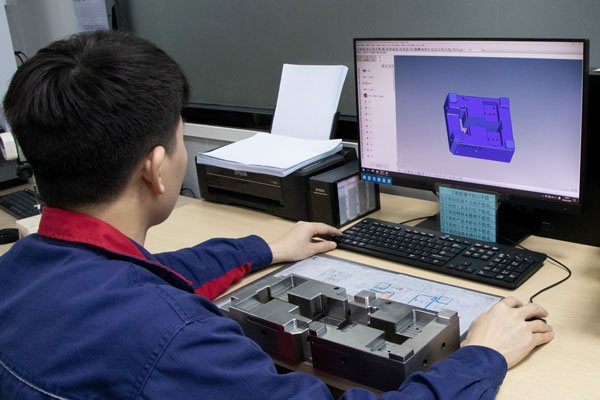
Modern injection mold design has entered the era of “CAE simulation + 3D printing validation.” Engineers should leverage tools like Moldflow and Moldex3D for multi-physics coupling analysis, complemented by rapid prototyping for runner system verification. Remember: Every 0.1mm adjustment in gate position can cause 30% fluctuations in product quality. Master these nine rules to upgrade your design from “trial-and-error” to “precision-guided.”
Interactive Topic: Share your “counterintuitive” challenges in runner system design! Comment with your “pitfall-avoidance” stories.
