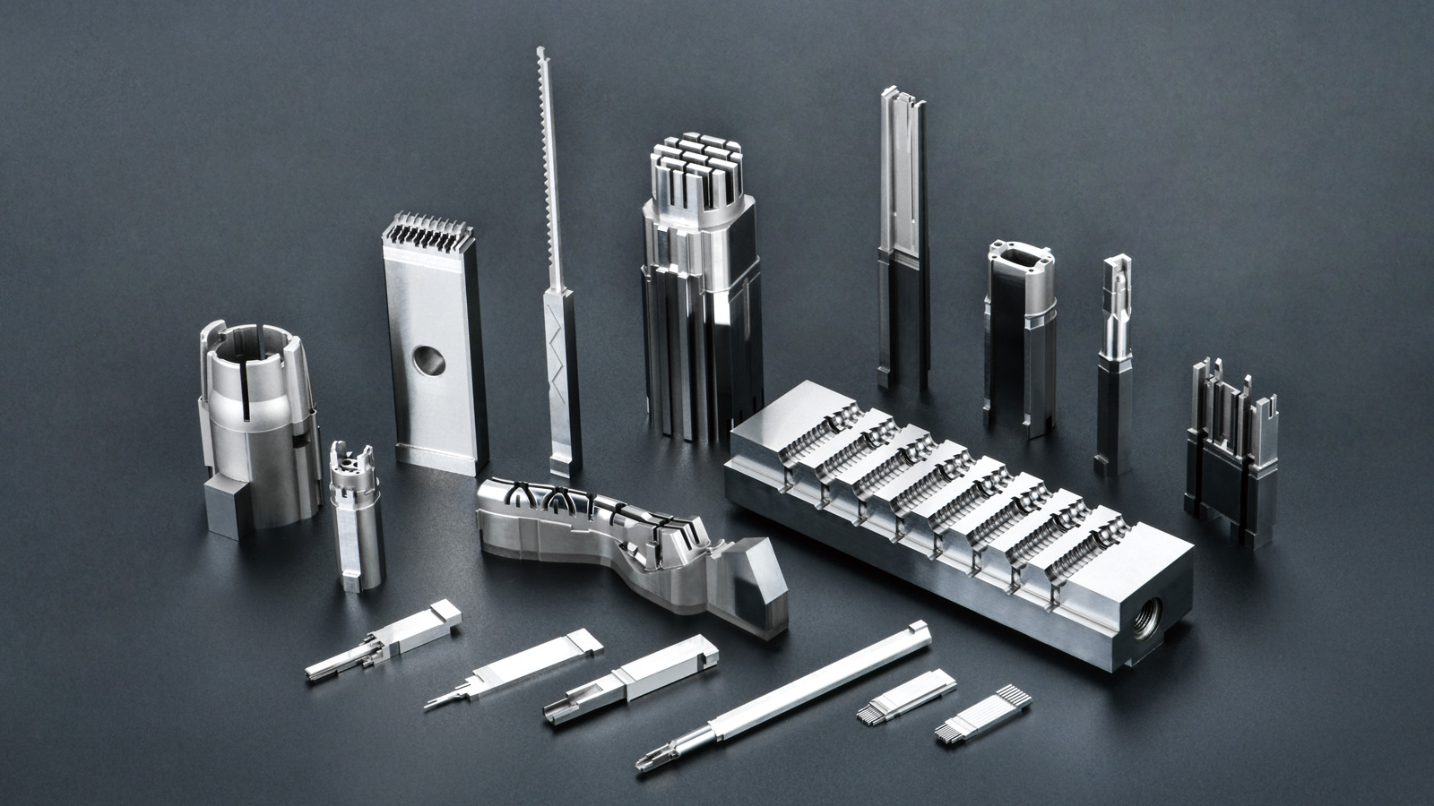
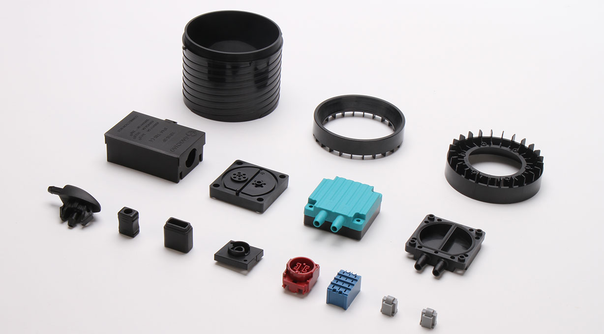





Flash (also known as burr or flying edge) is one of the most common quality defects encountered during injection molding production. The occurrence of flash is primarily related to two core factors: mold clearance and clamping force. When the mold clearance is excessive or the clamping force is insufficient, molten plastic overflows from the parting surface under high pressure, forming flash after cooling. Accurate root cause identification and effective resolution require a systematic analysis based on actual production conditions.
1. Mold Clearance: The Structural Root Cause of Flash
Flash caused by mold clearance issues typically appears uniformly distributed around the parting surface. The main causes include the following:
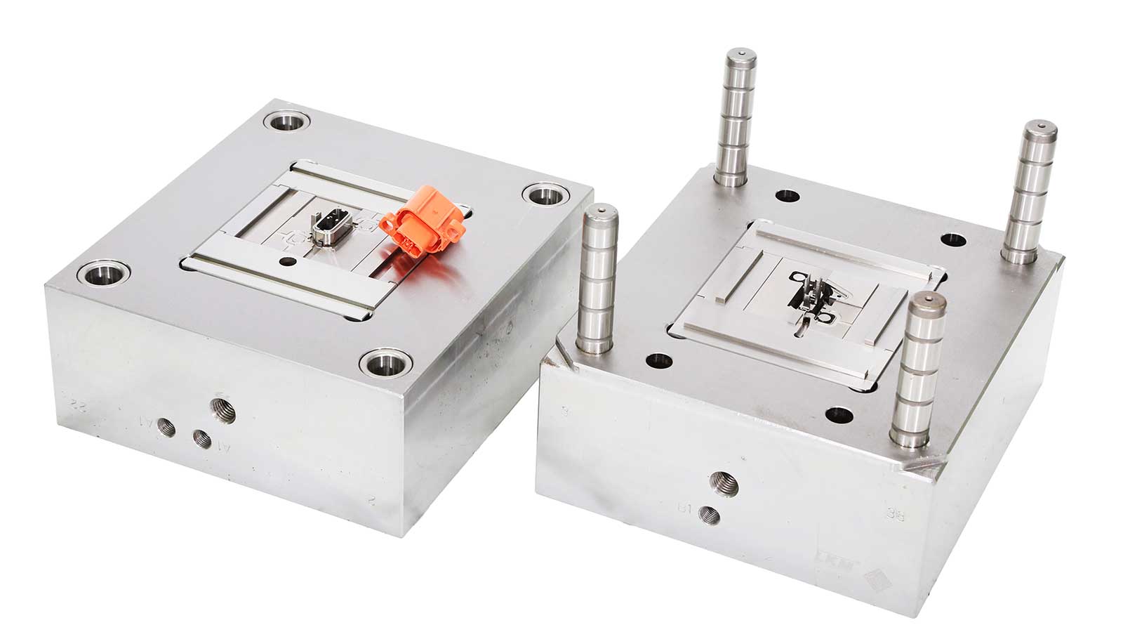
After prolonged use, the parting surface wears due to repeated opening and closing cycles, causing the clearance to increase. If the machining accuracy was insufficient during the mold manufacturing stage, if assembly errors exist, or if uneven thermal expansion occurs, local gaps will result. During mold inspection, red lead powder can be used to test the parting surface contact. If the clearance exceeds 0.03 millimeters, repair is required. For complex molds, special attention should be paid to the fit clearance of moving components such as sliders and lifters, as these areas are frequently prone to flash.
2. Insufficient Clamping Force: The Process-Related Trigger for Flash
When clamping force is insufficient, flash tends to be unevenly distributed and is particularly noticeable in high-pressure zones. The required clamping force must be calculated by considering the projected area of the product and the injection pressure, with a safety margin of twenty percent typically recommended.
Common causes of insufficient clamping force include improper machine tonnage selection, hydraulic system internal leakage, or template parallelism deviation. Before production begins, it is essential to confirm that the mold thickness matches the machine’s clamping capacity to avoid inadequate mold clamping from affecting the clamping effect.
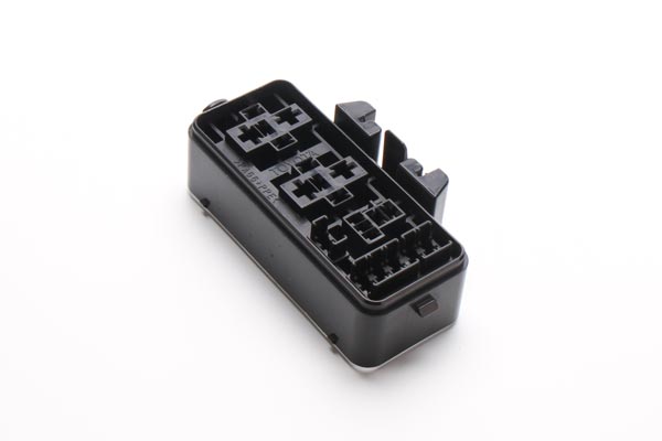
3. Other Key Process Factors Affecting Flash Formation
In addition to mold clearance and clamping force, the following process parameters also have a significant impact on flash:
Excessive material temperature reduces melt viscosity, making it easier for plastic to seep into microscopic gaps. Excessive injection speed causes pressure peaks that exceed the clamping force. Overly high holding pressure or excessively long holding time keeps the mold under sustained high pressure. Poor mold venting can cause localized gas pressure to push open the parting surface.
4. Systematic Solutions and Preventive Maintenance
For flash problems, the following systematic troubleshooting and resolution steps are recommended:
First, confirm whether the process parameter settings are reasonable and adjust the injection speed and holding pressure accordingly. Second, inspect whether the mold parting surface is clean and free of foreign objects. Third, measure the actual clamping force value and compare it with the theoretical calculated value. If necessary, arrange mold repair work, including lapping the parting surface or replacing guide pillars and bushings.
On the preventive maintenance front, it is recommended to perform regular maintenance on molds and injection molding machines, document the process parameters and issues from each production run, and gradually build a comprehensive process database to fundamentally reduce the recurrence rate of flash.
Frequently Asked Questions (FAQ)
Q: How can I quickly determine whether flash is caused by mold clearance or insufficient clamping force?
A: If the flash is uniformly distributed at fixed positions on the parting surface, it is most likely a mold clearance issue. If the flash is unevenly distributed and changes with injection pressure adjustments, it is most probably due to insufficient clamping force.
Q: At what clearance level must the mold parting surface be repaired?
A: Generally, if the parting surface clearance exceeds 0.03 millimeters, repair is required. This can be detected using the red lead powder test method or by direct measurement with feeler gauges.
Q: What is the recommended safety margin for clamping force?
A: The industry standard recommends retaining a safety margin of twenty percent. The calculation should consider the product’s projected area and the actual injection pressure to ensure sufficient clamping force.
Q: Besides mold clearance and clamping force, what other process parameters can cause flash?
A: Excessive material temperature, overly fast injection speed, excessive holding pressure or overly long holding time, and poor mold venting can all aggravate flash formation and require comprehensive control during production.
Q: How much does preventive maintenance help in reducing flash?
A: The benefit is very significant. By performing regular maintenance on molds and equipment, and by recording and analyzing process data, potential risks can be identified in advance, reducing the frequency of flash occurrence at the source.