


Precision injection mold design dictates production efficiency, component quality, and unit cost in modern manufacturing. A structured injection mold design process mitigates production risks, reduces tooling iteration costs, and accelerates time-to-market for plastic components across automotive, medical, and consumer electronics industries.
Comprehensive Part Review and DFM Optimization
The injection mold design workflow starts with evaluating part geometry through Design for Manufacturability (DFM) analysis. Engineers analyze wall thickness uniformity, draft angles, rib structures, and parting lines to ensure moldability. Identifying potential molding defects early—such as sink marks, void formation, or excessive deformation—prevents costly tool modifications after steel machining begins. Polymer shrinkage rates directly influence cavity sizing, requiring precise material selection data during initial engineering.
Core, Cavity, and Feed System Architecture
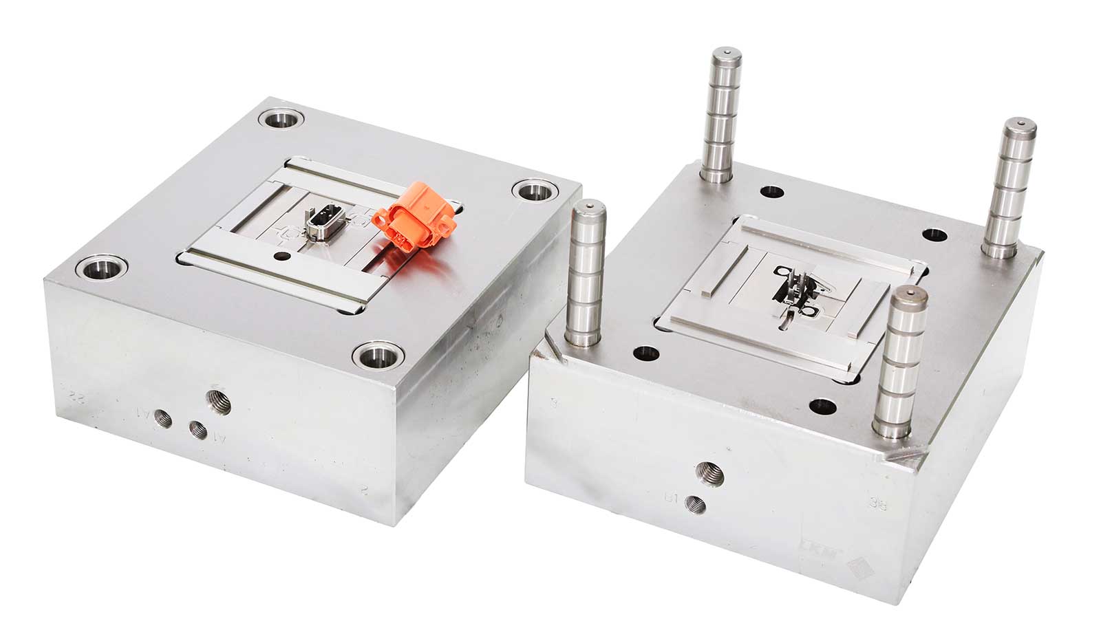
Establishing the parting line divides the core and cavity inserts, forming the fundamental structure of injection mold design. Engineers select appropriate feed systems based on production volume, resin characteristics, and visual surface standards. Cold runner systems offer lower initial tooling investment for mid-volume production, while hot runner systems minimize scrap material, reduce cycle times, and optimize melt pressure distribution in high-volume applications. Strategic gate placement ensures balanced filling, prevents weld lines in critical stress areas, and minimizes cosmetic blemishes.
Thermal Management and Ejection Mechanics
Cooling system layout governs over 70% of the injection molding cycle time and directly impacts part warpage. Optimized cooling channel placement—including conformal cooling circuits manufactured via additive techniques when necessary—maintains uniform mold temperature distribution. Concurrently, the ejection system design incorporates ejector pins, sleeve ejectors, or stripper plates tailored to part geometry. Proper mechanical stroke calculation and guide pin alignment prevent mechanical binding and component distortion during part release.
Moldflow Simulation and Virtual Validation
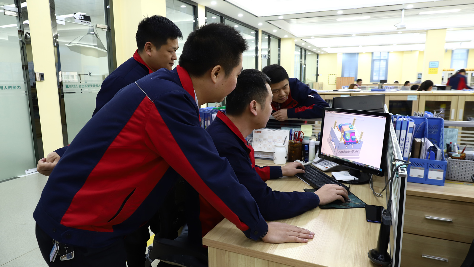
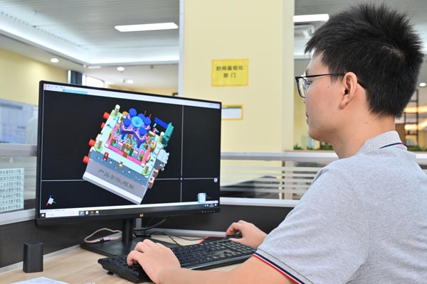
Advanced computer-aided engineering (CAE) tools validate the injection mold design before physical machining. Moldflow analysis simulates melt front progression, packing pressure, thermal distribution, and volumetric shrinkage. Virtual simulation highlights potential air traps, hesitation lines, and structural stress concentrations. Engineers refine gate sizing, runner dimensions, and cooling layouts based on empirical simulation data, eliminating trial-and-error iterations during physical sampling.
Tooling Fabrication, T1 Trial, and Process Qualification
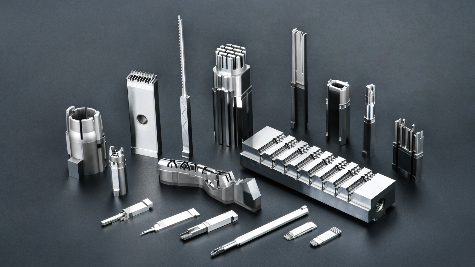
Upon final design freeze, 3D CAD models convert into CNC milling, EDM (Electrical Discharge Machining), and precision grinding toolpaths. Toolmakers assemble cavity blocks, ejector sets, and hot runner manifolds to strict dimensional tolerances. The initial mold trial (T1 sampling) tests tool functionality under production conditions. Dimensional inspection reports evaluate part compliance, guiding minor steel adjustments before final tool sign-off and full-scale production release.
Frequently Asked Questions
How long does the injection mold design process typically take? Standard injection mold design requires 1 to 3 weeks depending on part complexity, cavity count, and feed system architecture. Complex automotive or multi-cavity medical molds requiring advanced simulation may extend design lead times.
Why is DFM analysis critical before starting injection mold design? DFM analysis identifies geometric features that cause molding defects, excessive cycle times, or tool binding. Resolving wall thickness variations, draft angle limitations, and gate locations during design saves significant modification costs and prevents schedule delays.
What is the difference between hot runner and cold runner injection mold design? Cold runner designs solidify plastic in the feed channels during every cycle, requiring runner removal and recycling. Hot runner designs keep the melt fluid within heated manifolds, delivering plastic directly into the cavity to eliminate runner waste and shorten cycle times.